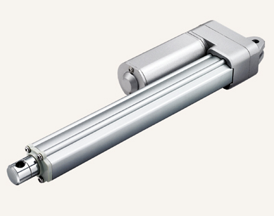
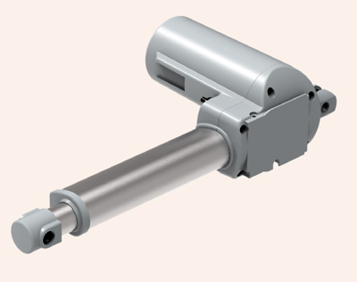
Linear Actuators
We are Manufacturer, Supplier, Exporter of Linear Actuators, Linear Actuator Units, Ball Screw Driven Linear Actuators, Belt Driven Linear Actuators, Linear Drives, Linear Stages and our setup is situated in Satara, Maharashtra, India. Majorly we serve our customers from ALL OVER INDIA including Metro Cities like Mumbai, Delhi, Kolkata, Chennai, Bangalore, Hyderabad, Ahmedabad, Pune, Surat.
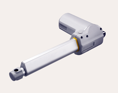
| Max. load | 10,000N (push) |
| 4,000N (pull) | |
| Max. speed at Max. Load | 3.2mm/s |
| Max. speed at no Load | 39.0mm/s |
| Retracted Length | ≥ Stroke + 163mm |
| IP Rating | IP66W |
| Certificate | IEC60601-1, ES60601-1, |
| EN60601-1-2, EMC | |
| Stroke | 25~1000mm |
| Options | Safety nut, quick release, Reed, Hall sensors |
| Voltage | 12/24/36V DC; 24V DC (PTC) |
| Color | Black or grey |
| Operational Temperature Range | +5°C~+45°C |
| Voltage of Motor | 12, 24, 36, 48V DC, or |
| 12, 24, 36, 48V DC (PTC) | |
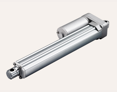
| Maximum Load | 1,000N in pull and push |
| Maximum speed at full Load | 51mm/s (with 120N in a push or pull condition) |
| Stroke | 20~1000mm |
| Minimum Installation Dimension | ≥ Stroke + 105mm (without output signals) |
| Color | Silver |
| Certificate | IEC60601-1, ES60601-1, EMC |
| Operational Temperature Range | +5°C~+45°C (Load < 500N) |
| -25°C~+65°C (Load ≥ 500N) | |
| Operational Temperature Range at full Performance | +5°C~+45°C |
| IP Rating | Up to IP66D |
| Options | POT, Reed, Hall sensors |
| Compact size for Limited Space |
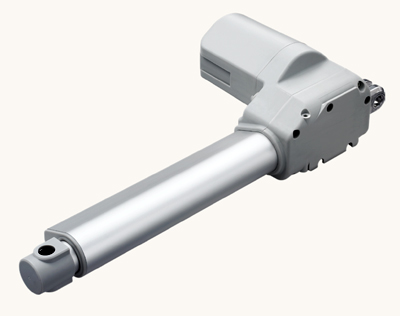
| Voltage of Motor | 12, 24, or 36V DC |
| Maximum Load | 10,000N in push |
| Maximum Load | 4,000N in pull |
| Maximum speed at full Load | 23.4mm/s |
| (with 1,000N in a push or pull condition) | |
| Stroke | 25~1000mm |
| Minimum Installation Dimension | ≥ Stroke + 171mm |
| Color | Black or grey |
| IP Rating | Up to IP66W |
| Certificate | IEC60601-1, ES60601-1, IEC60601-1-2, EMC |
| Operational Temperature Range | +5°C~+45°C |
| Options | Safety nut, Hall / Reed sensor(s) |
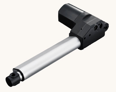
| Voltage of Motor | 12, 24, 36V DC or 24V DC (PTC) |
| Maximum Load | 6,000N in push |
| Maximum Load | 4,000N in pull |
| Maximum speed at full Load | 23.4mm/s |
| (with 1,000N in a push or pull condition) | |
| Stroke | 25~1000mm |
| Minimum Installation Dimension | ≥ Stroke + 163mm |
| Color | Black or dark grey |
| Certificate | UL962, EMC |
| Operational Temperature Range at full performance | +5°C~+45°C |
| For direct-cut System | Can function without control box |
| Max. Load | 3,500N (push/pull) |
| MaVx. speed at max.Lload | 6.2mm/s |
| Max. speed at no Load | 23.5mm/s |
| Retracted Length | ≥ Stroke + 112mm |
| IP Rating | IP66 |
| Certificate | IEC60601-1, ES60601-1, IEC60601-1-2, UL962, EMC |
| Stroke | 20~600mm |
| Options | POT, Hall sensor(s) |
| Voltage | 12, 24, 36, 48V DC |
| Color | Silver |
| Operational Temperature Range at full Performance | +5°C~+45°C |
| Voltage of Motor | 24V DC, 24V DC (PTC) |
| Maximum Load | 8,000N in push |
| Maximum Load | 3,000N in pull |
| Maximum speed at Full Load | 16.2mm/s |
| (with 2,000N in a push / pull condition) | |
| Stroke | ≥ 25~450mm |
| Minimum Installation Dimension | ≥ Stroke + 157mm |
| Color | Black or grey |
| IP Rating | Up to IP66W |
| Certificate | IEC60601-1, ES60601-1, IEC60601-1-2 |
| Operational Temperature Range at full Performance | +5°C~+45°C |
| Options | Safety nut, Hall sensors |
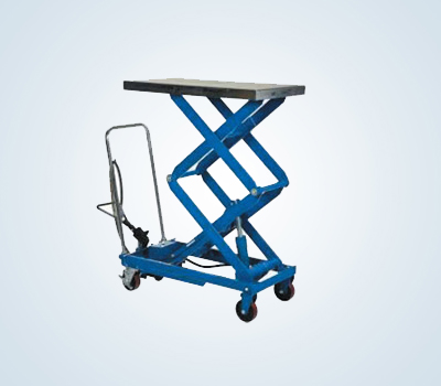
These Linear Actuators are used for material handling equipments as well as scissor lifter applications
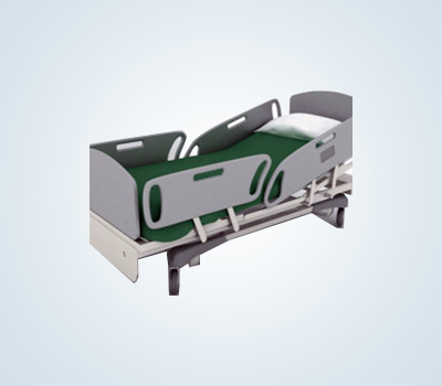
Medical series Linear Actuator is driven by worm & gears and easy to install with long service life, Low noise and free maintenance. These Linear Actuators help smoothly in adjusting medical bed, surgical beds, nursing beds, Dental & Wheel chairs
The Linear Actuator is applied in a Solar Tracker where in it helps to track the sun as it moves on its path through the sky. These Linear Actuators has minimum level of maintenance, low power consumption and stable quality performance
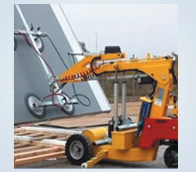
The industrial series Linear Actuators are designed to be strong wear resistance, high duty, water proof and easy installation which can be used in harsh environment without damaging any electronic parts
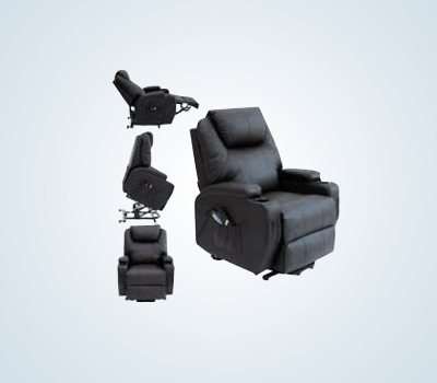
These Linear Actuators support you to design more adjustable and comfortable furniture, such as massage, multi functional sofas, TV/ Light Lifter or a system with additional features.
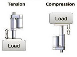
Liner Actuator can be used in tension, compression or combination tension/compression applications Examples of tension and compression are shown on left
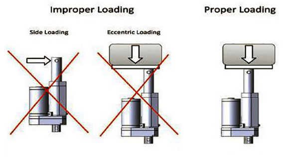
It is important to mount the actuator so that side loading and eccentric loading are avoided. To optimize the performance and are of the actuator. it should be mounted so that the load is applied along the Longitudinal axis of the transiating tube. Examples of proper and improper loading arrangements are shown below
If you have any query related our products ... We are available
Contact Us
